Author: Site Editor Publish Time: 2026-08-11 Origin: Site
Industrial component failure driven by severe wear, corrosive environments, and extreme thermal cycling results in massive unplanned downtime and replacement expenses annually. Specifying a surface engineering solution requires balancing strict metallurgical requirements with production economics. Over-engineering leads to bloated unit expenses, while under-specifying results in premature catastrophic coating failure, cracking, or delamination. You cannot afford to guess when protecting critical infrastructure.
To select the optimal thermal spray method, engineering and procurement teams must evaluate process capabilities against specific failure modes, substrate limitations, and lifecycle economics. This requires weighing high-performance outcomes against factors like HVOF operating cost. Understanding the distinct mechanical advantages of each spray process ensures your components survive their intended operational environments without unnecessary financial waste.
Process-to-Failure Alignment: Selection must begin with the primary degradation mechanism; plasma spray excels for thermal barriers, arc spray for large-scale corrosion, and HVOF for severe abrasion and wear.
Economic Realities: Lifecycle economics must dictate decisions. The high initial HVOF operating cost is frequently offset by extended component lifespans in critical applications.
Microstructural Integrity: Coating density, bond strength, and porosity levels are directly dictated by the chosen kinetic and thermal energy of the spray process.
Implementation Prerequisites: Even the most advanced thermal spray process will fail without rigorous, standardized surface preparation and precise feedstock selection.
Table of Contents
We evaluate parts on the shop floor based on how they actually fail in service. When a scored hydraulic cylinder or a blown-out pump casing lands on the inspection table, the first job is identifying the exact degradation mechanism. You have to frame the operating environment accurately before even thinking about spray equipment.
Wear is highly specific. Abrasive wear happens when hard particles like sand or ore physically gouge the metal. We see this constantly in mining slurry pumps and agricultural tillage tools. To stop it, you need extreme hardness, which usually points toward tungsten carbide applied with high kinetic energy. Adhesive wear, or galling, occurs when two metal surfaces slide against each other under heavy load, micro-welding and tearing apart. Think of valve stems or threaded connections. You fix this by applying dissimilar metals or materials with low friction coefficients.
Erosive wear involves high-velocity fluids carrying fine particulates that wash away the substrate. Boiler tubes and hydro-turbine runners face this daily. Fretting wear occurs when components undergo high-frequency, low-amplitude micro-oscillations, like bearing housings vibrating under load. This micro-movement tears out microscopic particles that oxidize and act as an abrasive lapping compound. The kinetic energy of the chosen spray process dictates the final coating density, which directly determines how well the part resists these specific wear modes.
Corrosion eats components alive if you misjudge the environment. We break this down into galvanic, chemical, and high-temperature oxidation. Galvanic corrosion requires a sacrificial anodic layer. We often spray zinc or aluminum on large infrastructure like bridges or offshore platforms to handle this. Chemical corrosion is harsher. If a part sits in an acidic bath or handles caustic fluids, you need an inert barrier.
High-temperature oxidation happens in gas turbines and exhaust stacks, requiring specialized superalloys that form protective oxide scales. In marine environments, chlorides attack the grain boundaries of susceptible stainless steels under tensile stress, causing chloride stress corrosion cracking. The absolute rule for chemical and oxidation protection is low porosity. If your coating has interconnected pores, the corrosive media will bypass the coating, attack the base metal, and cause the entire protective layer to spall off in sheets.
Heat destroys base metal properties. You must define the exact operational temperature thresholds. Components operating in combustion zones require Thermal Barrier Coatings (TBCs). These are usually ceramic layers that insulate the metal, manage thermal shock, and handle rapid heat dissipation.
A major field issue is the coefficient of thermal expansion (CTE). If the coating expands at a different rate than the steel underneath it during a heat cycle, the internal stress will shear the coating right off the part. We use metallic bond coats to bridge this CTE gap and provide a mechanical transition zone between the substrate and the ceramic topcoat.
You cannot specify a coating without hard numbers. Determine how many cycles until failure is acceptable. Define the maximum allowable wear rate in thousandths of an inch per year. Document specific chemicals, pH levels, and abrasive particle sizes the part will encounter. Establishing these metrics prevents you from applying a high-end aerospace coating to a part that only needs basic dimensional restoration.
Thermal spray is a broad term covering several distinct technologies. They all melt a feedstock and shoot it at a part, but the energy sources and particle velocities vary wildly.
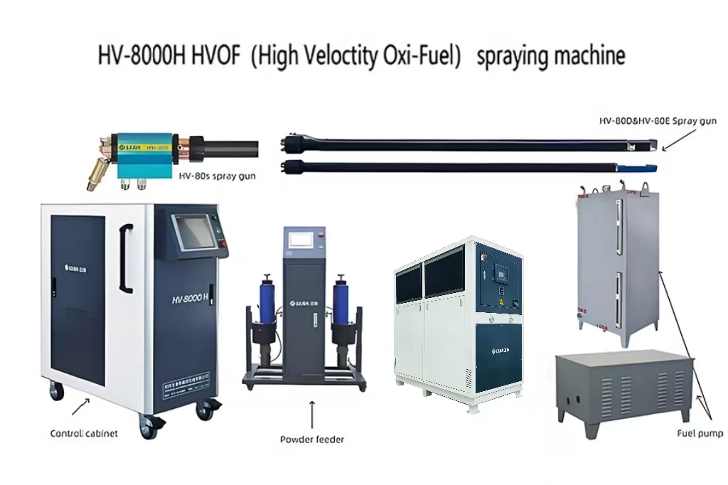
The facility requirements dictate what you can actually run. Electrical methods like Plasma and Arc spray need massive power supplies, robust electrical grids, and heavy-duty water chillers. Combustion methods like HVOF and Flame spray run on pressurized fuel gases, bulk liquid oxygen, and require serious exhaust and acoustic handling. A supersonic flame is deafening. These infrastructure demands set your baseline operational footprint.
Plasma spray uses an electrical arc to ionize inert gases like argon or nitrogen, creating a plasma plume. The temperatures inside that plume exceed 15,000 degrees Celsius, melting almost any known material.
Best Fit: We use plasma primarily for high-melting-point ceramics. If you need to spray zirconia or alumina for thermal barriers on turbine blades, plasma is the tool.
Limitations: The particle velocity is relatively low compared to combustion methods, resulting in higher porosity. The equipment is highly complex, requiring precise gas flow control and massive electrical draw.
HVOF mixes oxygen with a fuel gas like kerosene, propylene, or hydrogen in a combustion chamber. The expanding gases force the powder feedstock out of a converging-diverging nozzle at supersonic speeds. The particles might not be fully molten, but they hit the part so hard they mechanically forge together.
Best Fit: This is the undisputed king of severe wear and corrosion resistance. We use it to spray dense tungsten carbides and chrome carbides on mud motor rotors, ball valves, and hydraulic rods. It produces incredibly dense coatings with high bond strength and compressive residual stress.
Limitations: It is strictly line-of-sight. You cannot spray inside small bores. The heat input to the part is massive, requiring aggressive liquid carbon dioxide or air cooling to prevent warping the substrate.
Arc spray feeds two electrically conductive wires into a gun. A direct current arc jumps between the wire tips, melting them. A jet of compressed air blows the molten droplets onto the part.
Best Fit: Arc spray lays down material faster than almost anything else. We use it for large-scale corrosion protection on structural steel and for building up worn bearing journals quickly.
Limitations: You can only spray materials that conduct electricity and can be drawn into a wire. The coatings have moderate porosity and lower bond strength than high-velocity methods.
This is the oldest and simplest method. An oxy-acetylene or oxy-propylene flame melts a wire or powder, and compressed air pushes it forward.
Best Fit: Localized, low-stress repairs. It is great for applying easily machinable coatings like babbitt for plain bearings or doing quick dimensional build-ups on non-critical shafts.
Limitations: The particle velocity is very low. This yields the lowest bond strength and highest porosity of the major processes. We never use it for severe industrial wear.
Process | Energy Source | Primary Advantage | Typical Applications | Relative Porosity |
|---|---|---|---|---|
Plasma Spray | Electrical Arc / Ionized Gas | Extreme temperature capability | Thermal barrier coatings, ceramics | Moderate (2-5%) |
HVOF | Combustion (Supersonic) | High kinetic impact, dense coatings | Severe wear, hardbanding, carbides | Very Low (<1%) |
Twin Wire Arc | Electrical Arc / Compressed Air | High deposition rate, economical | Large area corrosion protection | Moderate to High (3-8%) |
Flame Spray | Combustion (Subsonic) | Simple setup, localized repair | Dimensional rebuilds, machinable layers | High (5-10%) |
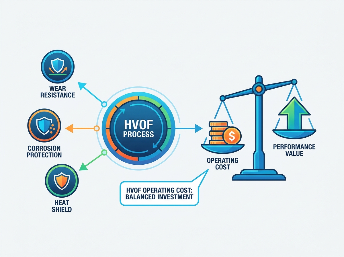
You have to justify the expense of premium coatings. Analyzing the direct shop expenses against the long-term field benefits is the only way to make an informed engineering decision. Understanding the nuances of HVOF operating cost reveals exactly when the investment makes sense.
Running an HVOF cell is resource-intensive. Consumables are the biggest factor. You are burning massive volumes of pure oxygen and fuel gas continuously. The premium carbide powders are highly engineered and expensive to procure. Deposition efficiency is a major cost driver here. In HVOF, the deposition efficiency for carbide powders typically ranges from 40% to 60%. This means up to half of the powder you purchase ends up in the dust collector. You have to factor this material loss into the overall job expense.
Equipment maintenance is another major factor. The extreme combustion pressures and temperatures erode copper nozzles and combustion chambers quickly. You have to replace these hardware components regularly to maintain spray parameters. Furthermore, the cooling infrastructure draws significant power. When you look at throughput, the hourly rate is high, but you have to balance that against the high deposition efficiency and the actual time the part spends in the booth.
Looking only at the invoice for the coating job is a mistake. You have to evaluate the Mean Time Between Failures (MTBF) in the field. Take a pump impeller handling abrasive mine tailings. An uncoated steel impeller might wash out in three months. A flame-sprayed part might last six. An HVOF-coated impeller can easily run for two years. Calculate the financial impact of avoiding just one unplanned shutdown, including the labor to pull the pump and the lost production time. In severe environments, the downtime mitigation heavily outweighs the initial HVOF operating cost.
You need a comparative matrix to guide procurement. Capital Expenditure for HVOF and Plasma is high due to the complex gas delivery systems, mass flow controllers, and safety infrastructure. Arc spray equipment is much simpler and cheaper to install. Operational Expenditure is highest for HVOF because of the continuous gas consumption and the price of carbide powders. However, when you evaluate the yield in a high-wear environment, HVOF consistently outperforms the others. If the component sits in a low-stress, static environment, Arc spray provides better economic alignment. If extreme heat is the primary failure mode, Plasma is the only viable option, regardless of the capital expenditure.
Coating specifications on a drawing must translate directly into physical performance in the field. We evaluate thermal spray processes based on specific microstructural features that dictate how the coating behaves under load.
Porosity determines permeability and structural integrity. The velocity of the spray process dictates the final density. HVOF accelerates particles to supersonic speeds, resulting in coatings with less than 1% porosity. The particles smash together so violently that voids are eliminated. Flame spray operates at subsonic velocities, yielding porosity levels that can exceed 5%.
You must map these porosity levels to your desired outcomes. Low porosity is mandatory for chemical corrosion barriers to prevent acids from reaching the substrate. Conversely, controlled porosity is sometimes engineered on purpose. In lubricated wear applications, a slightly porous coating retains oil, preventing dry starts.
Thermal spray adhesion relies on mechanical interlocking. There is no welding or metallurgical bonding taking place. The molten or semi-molten particles impact the roughened substrate, rapidly cool, shrink, and lock into the surface asperities. HVOF provides the highest bond strength due to its extreme kinetic impact.
You also have to watch the substrate thermal limits. The chosen process must not alter the heat treatment, temper, or mechanical properties of the base metal. We use aggressive air jets or liquid carbon dioxide cooling during the spray process to keep the substrate temperature well below critical metallurgical thresholds.
Material selection must align with both the process capabilities and the failure mechanism. You cannot spray ceramics effectively with HVOF because it lacks the thermal energy to melt them. You cannot achieve dense carbide coatings with Flame spray because it lacks the kinetic energy to forge them. Align material families with their optimal processes.
Material Family | Optimal Process | Primary Function | Common Industrial Application |
|---|---|---|---|
Tungsten Carbide | HVOF | Severe Abrasion Resistance | Mud Motor Rotors, Gate Valves |
Yttria-Stabilized Zirconia | Plasma Spray | Thermal Barrier | Gas Turbine Blades, Aerospace |
Zinc / Aluminum | Twin Wire Arc | Galvanic Corrosion | Bridge Infrastructure, Piping |
Babbitt / White Metal | Flame Spray | Sacrificial Wear | Plain Bearings, Compressor Shafts |
Even the perfect process and material combination will fail if the shop floor execution is sloppy. Strict adherence to preparation and quality control protocols prevents catastrophic field failures.
Because thermal spray relies on mechanical adhesion, surface preparation is the most critical step. You must execute rigorous grit blasting to achieve the correct surface profile.
Solvent clean or thermally bake the component to remove all oils, greases, and cutting fluids.
Mask all areas not requiring coating using specialized high-temperature tapes or custom metal fixtures.
Grit blast the target surface using angular aluminum oxide or chilled iron grit to achieve a 3 to 4 mil anchor profile.
Remove all residual blasting dust using clean, dry, oil-free compressed air.
Apply the thermal spray coating immediately to prevent flash oxidation of the freshly blasted surface.
Round steel shot will not create the necessary jagged anchor pattern. If you ignore surface prep standards, or if you let the part sit and oxidize between blasting and spraying, the coating will delaminate.
Residual stress dictates the maximum coating thickness and fatigue life. You must understand the mechanics of tensile versus compressive stress. Plasma spray typically generates tensile stress. As the fully molten particles hit the part and cool, they want to shrink. The rigid substrate prevents this, creating tension. This limits how thick you can spray before the coating cracks.
HVOF generates compressive stress. The high-velocity solid particles act like shot peening, hammering the previous layers. This compressive state allows for thicker, crack-free applications. Mitigation tactics include precise temperature control, matching the coefficients of thermal expansion, and strictly adhering to optimized thickness limits.
Looking at a coated part tells you nothing about its integrity. You must implement standardized evaluation metrics. Utilize ASTM C633 for destructive bond strength testing on companion coupons. Perform metallographic cross-sectioning. We cut, mount, and polish samples to accurately measure porosity and verify the coating-substrate interface under a microscope.
Conduct microhardness testing to ensure the applied material meets the required Vickers or Rockwell specifications. Incorporate functional durability testing protocols like Salt Spray testing (ASTM B117) to validate corrosion resistance, or Taber Abrasion testing to confirm wear performance before putting the component into service.
Define the primary failure mode (wear, heat, or corrosion) and establish strict durability metrics before selecting a process.
Select the required feedstock material family that directly combats the identified degradation mechanism.
Match the chosen material to the capable spray process, accounting for the infrastructure divide between electrical and combustion methods.
Validate the lifecycle economics, ensuring factors like HVOF operating cost align with the required component lifespan and downtime mitigation goals.
Engage with a qualified thermal spray coating engineer to conduct a metallurgical review, request sample coupon testing, and formalize a rigorous process specification.
A: The primary drivers are the massive consumption rates of pure oxygen and fuel gases like kerosene or hydrogen. The premium carbide powders used in HVOF are expensive, and deposition efficiency limits mean some powder is lost. Frequent replacement of wear parts also contributes significantly to running expenses.
A: Electrical methods like Plasma and Arc require high-voltage power supplies and extensive water-cooling systems. Combustion methods like HVOF and Flame spray require bulk storage for explosive fuel gases and oxygen, along with specialized exhaust and acoustic handling facilities due to supersonic noise levels.
A: Plasma spray is the optimal choice for high-temperature applications. Its extreme thermal energy can melt high-melting-point ceramics like zirconia and alumina. These materials create highly effective Thermal Barrier Coatings that protect underlying metal substrates from severe heat degradation.
A: High porosity allows corrosive liquids or gases to penetrate the coating and attack the base metal. This leads to sub-surface corrosion and rapid coating delamination. For corrosive environments, you must specify low-porosity processes like HVOF to create an impermeable barrier.
A: HVOF generally produces significantly higher bond strength than plasma spray. The supersonic velocity of HVOF particles creates immense kinetic energy upon impact, driving the particles deeply into the substrate's anchor profile. Plasma spray relies more on thermal energy, resulting in a slightly weaker mechanical interlock.
A: You must perform thorough chemical degreasing followed by aggressive abrasive grit blasting. The blasting must use angular media, such as aluminum oxide, to create a deep, jagged surface profile. This specific anchor pattern is absolutely critical for the mechanical adhesion of the coating.