Author: Site Editor Publish Time: 2026-08-11 Origin: Site
The success of a thermal spray coating operation depends heavily on facility infrastructure. Whether you apply protective layers to new production parts or remanufacture worn components, the physical layout dictates your yield. Under-engineered production layouts and inadequate utility sizing create severe bottlenecks. They compromise coating structures, causing porosity and bond strength failures, while introducing hazardous working conditions. When gas delivery systems fluctuate or cooling capacities fall short, component performance drops immediately. To prevent these failures, operators must design a facility framework that evaluates spatial workflow, intensive gas and electrical utility demands, and acoustic enclosures. You also need dedicated zones for routine upkeep, specifically HVOF spray gun maintenance. Proper planning transforms a standard shop floor into a high-yield, repeatable surface engineering environment.
Workflow Continuity: Optimal production line layouts physically separate surface preparation, spraying, and inspection zones to prevent cross-contamination while minimizing part-handling time for both high-volume OEM and variable repair workflows.
Utility Scalability: High-velocity and plasma systems require strictly regulated, high-volume utility drops (gases, chilled water, power); undersizing these at the design stage exponentially increases future CapEx and degrades coating quality.
Maintenance Integration: Dedicated, clean-environment bays for HVOF spray gun maintenance are mandatory to reduce unplanned downtime and ensure consistent powder feed and combustion dynamics.
Compliance & Safety: Acoustic isolation, combustible dust collection, and NFPA/OSHA-compliant gas storage must dictate the foundational footprint of the thermal spray cell.
Table of Contents
The primary goal of any industrial layout is achieving continuous, unidirectional part flow from pre-processing to final inspection without backtracking. Backtracking introduces severe logistical bottlenecks and increases the risk of component damage during transit. It also complicates production scheduling on the shop floor. A well-engineered thermal spray cell forces components to move logically through discrete stations. Parts enter the staging area, move into surface preparation, transition immediately into the acoustic spray booth, and exit into a cooling or metallurgical inspection buffer. This linear progression maximizes throughput and keeps heavy handling equipment moving in a single, predictable direction.
Layout requirements shift dramatically depending on the nature of the components being processed. Designing linear layouts works exceptionally well for high-volume new production parts, where every component follows an identical operational sequence. The footprint can be tightly compressed, minimizing the distance between the grit blast cabinet and the spray booth.
Conversely, incorporating flexible routing is necessary for repair and salvage operations. Remanufacturing workflows require additional pre-machining zones to remove damaged material, chemical stripping tanks, and dimensional inspection stations before the part ever reaches the surface preparation stage. The facility layout must accommodate these variable paths, allowing parts to bypass certain stations or loop through secondary machining without disrupting the primary high-volume production line.
Workflow Type | Pre-Processing Needs | Routing Structure | Buffer Zone Requirements |
|---|---|---|---|
High-Volume OEM Production | Standardized grit blasting and masking | Strictly linear, tightly compressed footprint | Minimal; parts move directly to inspection |
Component Remanufacturing | Pre-machining, stripping, NDT inspection | Flexible, loop-based routing | Large staging areas for variable cooling times |
R&D / Prototype Coating | Variable surface prep, custom masking | Modular stations with isolated access | Dedicated metallurgical lab proximity |
Physical isolation of distinct processes is non-negotiable in surface engineering. Isolating aggressive surface preparation, such as aluminum oxide grit blasting or laser cleaning, from the main spray booth ensures pristine substrate adhesion. If abrasive dust migrates into the coating zone, it settles on freshly prepared surfaces. This creates inclusions that severely reduce bond strength and cause premature coating delamination.
Establishing clean zones for masking, tooling preparation, and feedstock material handling further protects the integrity of the process. Masking tapes and compounds must be applied in a dust-free environment to ensure sharp coating transition lines. Positioning post-spray cooling buffers and metallurgical evaluation labs near the exit of the spray cell accelerates quality control. These labs test coating structure criteria, including bond strength, porosity, oxidation levels, hardness, and surface roughness. Immediate feedback from the lab allows operators to adjust spray parameters before running the next batch.
Moving heavy industrial components requires robust material handling infrastructure integrated directly into the facility architecture. Evaluating overhead crane access versus robotic part manipulation within the acoustic enclosure dictates the structural requirements of the booth roof and support columns. Overhead cranes require slotted roof designs in the acoustic enclosure, which complicates noise mitigation and dust extraction.
Calculating spatial requirements for multi-axis robotic arms and turntable clearances depends entirely on maximum part geometries. A six-axis robot requires sufficient envelope space to maintain a strict 90-degree spray angle and a precise standoff distance across complex topographies. The booth must provide enough clearance so the robot does not collide with the turntable, the component, or the booth walls during extreme articulation.
Determine the maximum dimensions and weight of the largest component expected in the cell.
Select a turntable or headstock/tailstock positioner rated for 150% of the maximum component weight.
Map the reach envelope of the robotic arm to ensure it can maintain a 12-inch to 16-inch standoff distance across the entire part surface.
Design the acoustic booth walls to sit at least three feet outside the maximum robotic reach envelope to prevent collision faults.
Utility infrastructure directly dictates coating quality. Operators map specific utility inputs to tangible coating outcomes. Dynamic pressure stability in fuel gas lines directly impacts coating density and oxidation levels. If a gas manifold is undersized, the ignition of a high-velocity torch causes a sudden pressure drop. This alters the stoichiometric ratio of the flame, leading to a cooler, oxygen-rich plume that oxidizes the feedstock powder and increases coating porosity. Consistent, high-volume utility delivery ensures the plume dynamics remain stable from ignition to shutdown.
Facility engineers ensure utility infrastructure supports the specific thermal spray processes dictated by the facility's coating selection matrix. Different technologies impose vastly different demands. Electrical plasma and wire arc systems require massive electrical drops and specific carrier gases like argon or helium. Combustion-based high-velocity systems rely on high-pressure liquid fuels, hydrogen, and massive volumes of oxygen. The infrastructure must be tailored to the exact equipment specifications, with manifolds and power supplies sized to handle peak operational loads rather than average consumption.
Thermal Spray Process | Primary Gas Demands | Electrical Requirements | Cooling Water Load |
|---|---|---|---|
Atmospheric Plasma Spray (APS) | Argon, Hydrogen, Helium | High (Up to 100 kW DC power supply) | Extreme (Requires high-capacity deionized chillers) |
High-Velocity Oxygen Fuel (HVOF) | Oxygen, Kerosene, Propylene, Hydrogen | Low (Primarily for controls and robotics) | High (Critical for combustion chamber stability) |
Twin Wire Arc Spray | Compressed Air, Nitrogen | Medium (Typically 300-600 Amps) | Low (Often air-cooled or minimal water cooling) |
Calculating precise flow rates and dynamic pressure requirements for oxygen, fuel gases, and carrier gases is a strict engineering task. Gas delivery systems maintain constant pressure at the torch head, regardless of tank levels or ambient temperatures in the storage yard.
Design hard-piped delivery lines with appropriate diameters to minimize pressure drops over long distances.
Install high-flow regulators and automated shut-off valves at the point of use inside the spray cell.
Integrate flash arrestors on all combustible gas lines to prevent flame propagation back to the bulk storage tanks.
Position bulk external tanks on reinforced concrete pads with clear access for delivery trucks, keeping them away from heavy traffic zones.
Sizing primary power drops requires analyzing the specific technology in use. High-amperage plasma power supplies demand heavy-duty, three-phase electrical infrastructure. They often require dedicated transformers to prevent voltage sags across the broader facility when the arc strikes. Combustion-based systems draw less primary power but still require stable electricity for robotic controllers, powder feeders, and extraction fans.
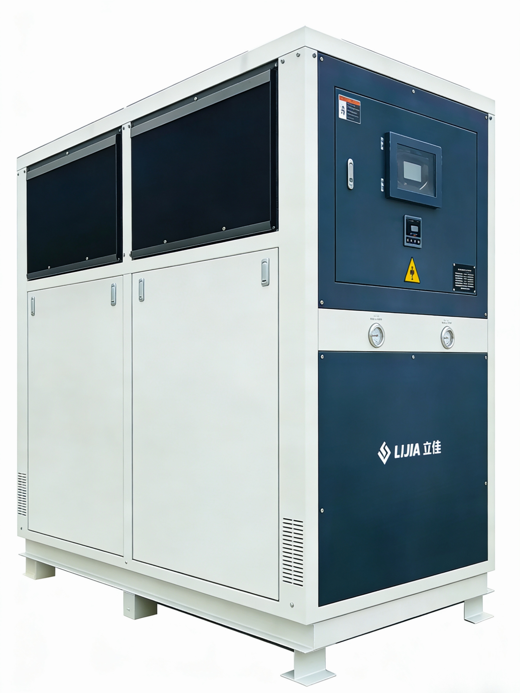
Specifying closed-loop industrial chillers is equally demanding. Engineers calculate the exact BTU/hr heat removal requirements to prevent torch degradation and maintain stable plume temperatures. Plasma and high-velocity torches generate extreme internal heat. If the cooling water flow or temperature fluctuates, internal components warp, O-rings melt, and the torch fails catastrophically. Chillers provide deionized or highly filtered water to prevent mineral scale buildup inside the delicate cooling channels of the torch.
Capturing overspray and maintaining negative pressure within the spray booth requires massive air movement. Engineers calculate the exact CFM requirements based on the booth volume and the specific spray process. Negative pressure ensures that toxic dust and metallic fumes cannot escape into the broader manufacturing facility when the booth doors open.
Selecting the correct extraction technology is a matter of safety and efficiency. Wet scrubbers are mandatory for highly reactive feedstock materials like aluminum or titanium, which pose severe explosion risks if collected dry. Dry cartridge collectors handle less reactive materials like tungsten carbide or stainless steel, provided they are equipped with appropriate pulse-cleaning mechanisms and HEPA secondary filters.
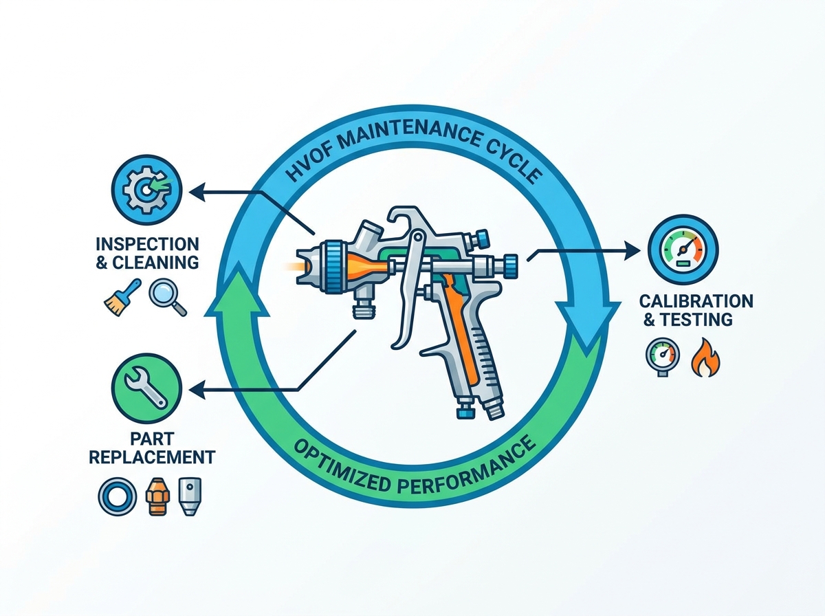
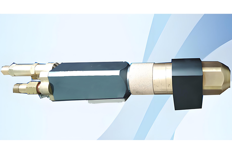
High-velocity oxygen fuel systems operate under extreme combustion pressures and temperatures, creating a harsh internal environment for the torch components. Due to these aggressive operating conditions, high-velocity torches require significantly more rigorous and frequent teardowns than standard arc or flame spray systems. Carbon buildup in the combustion chamber, thermal degradation of internal seals, and wear on the powder injection ports alter gas flow dynamics and degrade coating quality. Routine, meticulous upkeep is a fundamental requirement for process stability.
Performing delicate torch rebuilds on a dirty shop floor guarantees premature equipment failure. Facilities architect a clean, well-lit workstation physically separated from the abrasive dust and metallic overspray of the production floor. This dedicated bay ensures that internal mixing chambers and delicate O-rings remain free of contamination during assembly.
Integrating localized utility drops specifically for this zone streamlines the workflow. Compressed air lines for blowing out channels, dedicated water testing lines for checking cooling jacket integrity, and electrical outlets for diagnostic equipment allow technicians to perform comprehensive flow-testing and leak checks before the torch is mounted back on the robot.
Disconnect and cap all fluid, gas, and powder lines at the robot wrist.
Transfer the torch to the isolated clean-room maintenance bay.
Disassemble the combustion chamber and inspect all internal O-rings for thermal degradation or flattening.
Clean copper nozzles and mixing blocks in an ultrasonic bath to remove stubborn carbon deposits without scratching internal geometries.
Reassemble the torch using point-of-use inventory and perform a pressurized water leak test before returning it to production.
Efficiency in equipment upkeep relies heavily on organization. Designing point-of-use storage for consumables—such as O-rings, gas nozzles, powder ports, and mixing blocks—eliminates the time technicians spend walking to a central tool crib. Everything required for a complete torch rebuild sits within arm's reach.
Establishing a standardization protocol within the maintenance cell further ensures consistency. Dedicated bore inspection tools, such as illuminated magnifiers or borescopes, allow technicians to verify the internal condition of the barrel before reassembly. Having the right tools permanently stationed in the clean room prevents cross-contamination from other maintenance activities in the plant.
Integrating dedicated upkeep zones into the initial floor plan drastically reduces Mean Time to Repair (MTTR). When technicians have a clean, fully equipped environment, they execute a complete torch rebuild in a fraction of the time it takes in a disorganized shop. This clean-room approach prevents catastrophic torch failures during production runs. A single grain of abrasive grit trapped in a cooling seal causes a high-velocity torch to leak water into the combustion chamber, destroying the coating and potentially damaging the part. Proper infrastructure eliminates this risk entirely.
Treating safety and environmental compliance as an afterthought is a costly engineering mistake. The regulatory and safety hazards of retrofitting compliance measures after installation are severe. Attempting to route massive extraction ductwork or install blast-relief venting in a facility that was not designed for it compromises structural integrity and drastically increases installation costs. Safety systems dictate the foundational footprint of the thermal spray cell from day one.
Thermal spray processes, particularly plasma and high-velocity combustion, generate deafening noise levels frequently exceeding 130 dB. Prolonged exposure to this noise level causes immediate and permanent hearing damage. Mitigating this hazard requires custom-engineered acoustic enclosures.
Specify wall panels with high-density acoustic insulation and perforated inner skins to absorb high-frequency sound waves.
Install automated interlocking doors wired directly to the system PLC, ensuring the torch cannot ignite unless the heavy acoustic doors are fully sealed.
Utilize double-glazed, acoustically rated viewing windows to allow operators to monitor the process safely from the outside.
Design baffled ventilation intakes that allow massive airflow into the booth without letting noise escape into the shop.
Metallic overspray presents a severe fire and explosion hazard. Adhering to NFPA 484 standards for combustible metals is a strict legal and operational requirement. Fine metallic dust, particularly aluminum, titanium, and certain alloys, ignites spontaneously or explodes if suspended in the air and exposed to an ignition source.
Designing blast-relief venting into the ductwork and the booth structure directs the force of an accidental deflagration safely outside the building, protecting the operators. Specialized fire suppression systems, utilizing argon or specialized dry powders rather than water, integrate directly into the dust collection system and the booth itself to extinguish fires before they propagate through the ductwork.
The reliance on massive volumes of explosive fuels and inert carrier gases necessitates comprehensive leak detection infrastructure. Placing automated sensors for explosive gas accumulation near manifolds, inside the booth, and along the ceiling is mandatory. These sensors tie into the main control PLC to automatically shut down gas delivery and trigger high-speed ventilation if a leak is detected.
Oxygen depletion sensors are equally critical. Inert gases like argon are heavier than air and pool in confined spaces, trenches, or pits. If an operator enters an argon-filled pit to perform maintenance, they risk rapid asphyxiation. Proper floor-level ventilation and continuous atmospheric monitoring eliminate this hidden danger.
Conduct a comprehensive site audit to map existing gas flow rates, electrical amperage, and chiller capacities against your specific coating equipment requirements.
Draft a preliminary spatial footprint that strictly isolates surface preparation from the main spray booth to guarantee unidirectional part flow and prevent cross-contamination.
Construct a dedicated, clean-environment maintenance bay equipped with localized utility drops specifically for torch rebuilds and flow testing.
Install automated gas leak detection, oxygen depletion sensors, and NFPA-compliant dust collection systems before finalizing the booth layout.
Hire facility engineering partners with proven, field-tested expertise in thermal dynamics, acoustic mitigation, and combustible dust management.
A: Proper utility sizing and the physical isolation of surface preparation zones directly control critical coating evaluation criteria. If abrasive dust from blasting crosses into the spray zone, it compromises substrate adhesion. Stable gas and cooling utilities prevent flame fluctuations, directly ensuring consistent bond strength, low porosity, minimal oxidation, and uniform hardness.
A: The baseline needs include high-pressure, high-volume oxygen and liquid or gaseous fuel lines. The system also requires stable 3-phase power, high-capacity closed-loop chillers capable of removing extreme heat, and clean, dry compressed air for powder feeding and pneumatic controls.
A: Yes, but the layout must account for variable routing. Remanufacturing requires extensive pre-machining, chemical stripping, and dimensional inspection zones that are not needed for OEM parts. A flexible layout allows repair parts to loop through these stations without bottlenecking the linear flow of new production.
A: The footprint depends heavily on the maximum part size. It must account for the robot's maximum reach, turntable clearance, and safe standoff distances. Typically, a standard industrial setup requires a minimum 15x15 ft acoustic enclosure to allow full robotic articulation without collision risks.
A: High-velocity components are highly sensitive to contamination. Performing maintenance in a dedicated clean zone prevents ambient grit and metallic dust from compromising delicate O-rings and internal mixing chambers. A clean rebuild ensures stable combustion dynamics and prevents catastrophic torch leaks during operation.
A: Thermal spray facilities must comply with NFPA 484 standards for combustible metals. This includes using wet scrubbers to safely capture highly reactive materials like aluminum and titanium, implementing proper electrical grounding to prevent static discharge, and installing blast-relief venting in ductwork.
A: No. While some carrier gases overlap, plasma requires massive electrical drops and different primary gases like argon and hydrogen. High-velocity systems rely on high-pressure oxygen and liquid fuels. You must design separate, dedicated utility manifolds to handle the distinct demands of each process.