Author: Site Editor Publish Time: 2026-08-11 Origin: Site
Specifying industrial coating systems requires balancing strict performance tolerances with significant capital expenditure. Selecting an inadequate system leads to premature component failure, unacceptable porosity levels, and wasted investment. Engineering and procurement teams must navigate a fragmented market of thermal spray technologies, where vendor claims often obscure the practical trade-offs between thermal impact, kinetic energy, surface preparation requirements, and operational realities. This guide provides an evidence-based framework for evaluating thermal spray systems, detailing the operational realities of core processes, and offering a deep-dive technical evaluation of HVOF spray equipment for high-density, low-porosity applications.
Thermal spray is a family of processes; equipment selection must be dictated by the specific coating material (e.g., carbides vs. ceramics), the substrate’s thermal limitations, and the end-use application goals.
HVOF spray equipment delivers superior bond strength and minimal porosity for wear and corrosion applications by prioritizing kinetic energy over thermal energy.
Successful implementation requires matching the sophistication of the spray equipment with appropriate surface preparation tools, robotics, handling systems, and stringent quality control protocols.
Table of Contents
Engineers must establish a technical baseline before evaluating specific machinery. You need to understand how energy transfer dictates coating architecture. Thermal spray is a continuous coating process utilizing both thermal and kinetic energy. Combustible liquids, gases, or electrical currents melt the feedstock. The system then accelerates these particles toward a prepared substrate. The particles flatten upon impact, forming splats that interlock mechanically.
This differs fundamentally from electroplating or physical vapor deposition (PVD). Electroplating relies on chemical baths and ionic transfer, which limits thickness and introduces hydrogen embrittlement risks. PVD operates in a vacuum using vaporized materials, restricting component size and deposition rates. Thermal spray builds thicker coatings rapidly in an open atmosphere and accommodates a massive range of feedstock materials.
You must identify non-negotiable metrics for equipment evaluation. Do not rely on generic vendor specifications. Focus on your exact component requirements by following these evaluation steps:
Define required bond strength: Measure both adhesion to the substrate and cohesion between splats. High-stress applications demand maximum mechanical interlocking, often exceeding 10,000 psi.
Establish maximum allowable coating porosity: Corrosive environments require dense coatings. Interconnected porosity allows corrosive media to reach the substrate, causing under-film corrosion and catastrophic delamination.
Determine substrate heat tolerance: Thin-walled components warp under high heat. You must evaluate the risk of metallurgical alteration, phase changes, or loss of temper in the base metal.
Calculate required deposition rate: Production throughput dictates equipment sizing. High-volume lines need continuous, stable powder delivery and high spray rates to meet cycle times.
Verify industry specifications: Aerospace and defense sectors mandate strict adherence. You must comply with AMS, MIL-STD, or OEM-specific standards, which often dictate the exact equipment type and parameter windows.
No single thermal spray process solves every engineering challenge. You must match the energy profile of the equipment to the feedstock material. Understanding the physics behind each process prevents costly specification errors.
These represent the foundational technologies of the thermal spray family. They offer economical solutions for specific applications where extreme density is not the primary requirement.
Flame spray utilizes combustible gas mixtures, typically oxygen and acetylene, to melt wire or powder feedstocks. The flame temperature reaches approximately 3,000°C. Electric arc spray uses two conductive wires fed into a torch head. An electrical short circuit between the wires creates a localized arc, generating temperatures up to 5,000°C. Compressed air atomizes the molten metal and propels it forward at relatively low velocities.
These systems provide high deposition rates and require lower initial capital investments. However, they produce higher porosity levels (often 5-10%). Bond strengths remain relatively low compared to high-velocity methods, typically hovering around 2,000 to 4,000 psi. The coatings often contain higher oxide levels due to atmospheric exposure during the slow flight path.
Use these systems for dimensional restoration on non-critical shafts. They excel at basic corrosion protection using zinc or aluminum on large infrastructure components like bridges and offshore platforms.
Plasma technology handles materials with extreme melting points. It dominates the aerospace turbine sector for applying thermal barrier coatings.
These systems utilize an ionized gas plasma plume. An electric arc passes through a gas mixture, typically argon combined with hydrogen or helium. This strips electrons from the gas molecules. The resulting plasma generates extreme temperatures, with the core reaching up to 16,000°C. Powder feedstock injects directly into this plume, melting instantly and accelerating toward the target.
Plasma offers unmatched versatility. It easily melts refractory metals and advanced ceramics like yttria-stabilized zirconia. However, it presents high operational complexity. The systems require significant water cooling infrastructure to prevent torch meltdown. Coatings exhibit higher porosity compared to high-velocity methods, which is sometimes intentional for thermal insulation. The massive thermal load on the substrate requires careful management to prevent warping.
High-Velocity Oxygen Fuel technology revolutionized hardfacing by shifting the industry focus from thermal energy to kinetic energy.
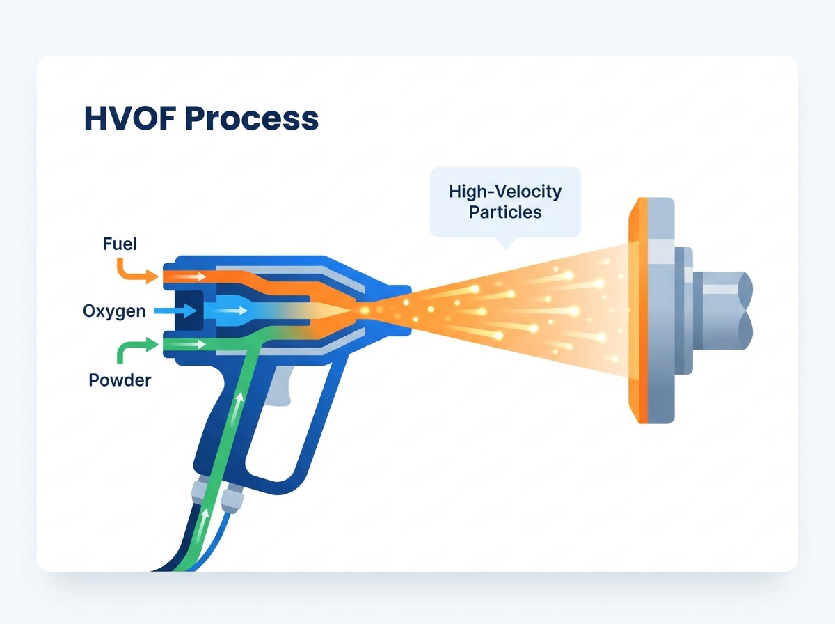
This process combusts oxygen and a fuel gas or liquid under high pressure within a confined chamber. The expanding exhaust gases exit through a converging-diverging DeLaval nozzle. This accelerates the gas stream to supersonic speeds, often exceeding Mach 2. Powder injects into this stream, absorbing heat and accelerating rapidly. The particles impact the substrate with massive kinetic energy.
The lower temperature prevents the degradation of complex carbide matrices, while the massive kinetic impact results in compressive residual stresses. This allows for exceptionally high density (often less than 1% porosity) and superior bond strengths exceeding 12,000 psi. We specify this process for tungsten carbides, chromium carbides, and superalloys in severe wear and corrosive environments.
While high-velocity systems balance thermal and kinetic energy, cold spray pushes entirely into the kinetic realm.
This is a purely kinetic process utilizing heated, high-pressure gas, usually nitrogen or helium. The gas accelerates un-melted powder particles through a nozzle to supersonic speeds. Upon impact, the particles undergo severe plastic deformation, bonding metallurgically and mechanically to the substrate without melting.
Cold spray offers zero thermal degradation of the substrate and virtually non-existent oxidation. It produces incredibly dense coatings. However, it remains limited primarily to ductile materials like copper, aluminum, and certain nickel alloys. Hard, brittle materials shatter upon impact in a pure cold spray process.
Industries like aerospace, oil and gas, and hydraulics default to high-velocity technology for severe wear applications. It serves as the primary replacement for hard chrome plating. Environmental regulations heavily restrict hexavalent chromium, making high-velocity systems a superior, compliant alternative. The process generates compressive residual stresses in the coating, allowing for thicker builds without spontaneous delamination.
You must choose between gas and liquid fuels when specifying HVOF spray equipment. This decision impacts facility infrastructure, operating parameters, and final coating density.
System Type | Typical Fuels | Combustion Pressure | Particle Velocity | Primary Advantages |
|---|---|---|---|---|
Gas-Fuel | Hydrogen, Propylene, Natural Gas | 60 - 120 psi | Mach 1.5 - 2.0 | Broader range of fine powders, slightly higher temperatures, easier facility integration. |
Liquid-Fuel | Kerosene (Aviation grade) | 100 - 200+ psi | Mach 2.0 - 3.0 | Denser coatings, thicker build capabilities, higher compressive stress, ideal for thick carbides. |
Gas-fuel systems operate at lower combustion chamber pressures and generate slightly higher flame temperatures. This makes them suitable for a broader range of finer powders and complex geometries. The gas infrastructure often integrates easily into existing industrial facilities using standard cylinder packs or bulk tanks.
Liquid-fuel systems, utilizing aviation-grade kerosene, generate higher combustion chamber pressures. They produce denser coatings and handle thicker build requirements effectively. However, they require more robust cooling systems, often demanding high-pressure chilled water loops. Fuel atomization must remain perfectly consistent, demanding rigorous maintenance of fuel pumps, filters, and delivery lines.
Evaluating the individual components determines long-term reliability and coating consistency. Do not overlook the peripheral hardware when specifying a system.
Spray Torches and Nozzles: Evaluate the barrel length. Longer barrels increase particle dwell time and velocity but require more cooling. Assess the cooling jacket design. Efficient cooling prevents premature nozzle degradation and O-ring failure. Monitor consumable wear rates closely, as degraded nozzles alter the flame geometry, introduce turbulence, and ruin coating integrity.
Powder Feeders: Consistent coating architecture requires precise powder delivery. Specify closed-loop mass flow control. This technology weighs the powder continuously during operation and adjusts the carrier gas automatically. This prevents pulsing, compensates for powder density variations, and ensures uniform splat formation.
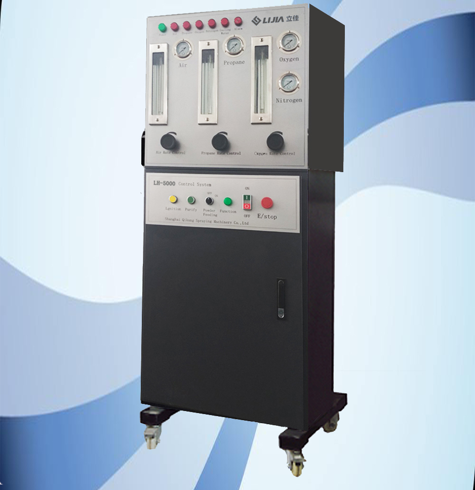
Control Consoles: Manual controls belong in the past. Modern applications require PLC-based automation with intuitive HMI touchscreens. You need real-time parameter monitoring and closed-loop control of all gases using mass flow controllers (MFCs). Data logging is non-negotiable for aerospace and military compliance. The system must record gas flows, pressures, and temperatures at one-second intervals for every coated component.
Equipment selection must follow the application requirements. Reverse-engineering the process by buying a machine and looking for parts to coat guarantees failure. Start with the material science and the operating environment.
The feedstock dictates the required energy profile. You cannot force a material through the wrong process and expect acceptable metallurgical results.
Material Category | Specific Examples | Mandated Process | Engineering Rationale |
|---|---|---|---|
Advanced Ceramics | Yttria-Stabilized Zirconia, Alumina, Titania | Plasma Spray (APS) | Requires extreme thermal energy (>10,000°C) to achieve a molten state. High-velocity systems cannot melt these materials. |
Carbides & Cermets | Tungsten Carbide (WC-Co), Chromium Carbide (Cr3C2-NiCr) | HVOF Spray Equipment | Requires high kinetic energy and lower heat. Excessive heat dissolves the carbide matrix into the binder, destroying wear resistance. |
Pure Metals & Alloys | Stainless Steel, Nickel, Aluminum, Zinc | Arc Wire, Flame, or HVOF | Process selection depends entirely on required density. Arc wire for basic corrosion; high-velocity for dense, machined surfaces. |
Thermal spray relies entirely on mechanical interlocking. Chemical adhesion does not occur. The substrate must provide an aggressive anchor profile for the splats to grip.
Investing in high-end machinery fails without proper surface preparation. You must invest equally in automated grit blasting equipment. The surface requires a specific roughness profile, typically measured between Ra 3.0 and 6.0 micrometers. You must use clean, sharp aluminum oxide grit, usually 24 to 60 mesh. Contaminated grit transfers oils or debris to the substrate, guaranteeing coating failure. Automated blasting ensures consistent profile depth and prevents localized over-blasting on complex geometries.
You must protect non-coated component zones. High-velocity particle impact destroys standard masking tapes instantly. Select appropriate thermal tapes reinforced with fiberglass or silicone for low-volume work. For high-volume production, engineer custom metal shadowing tooling. This physical barrier blocks the spray plume, reduces masking labor, and ensures sharp, repeatable coating transition lines.
You must evaluate the risk of substrate warping. Phase changes in the base metal ruin structural integrity and dimensional tolerances.
High-velocity processes mitigate thermal damage effectively because they rely on high particle velocity. The dwell time of the heat source on the substrate remains very short. However, you still need auxiliary cooling. Direct compressed air jets or liquid CO2 cooling nozzles onto the component during spraying. Monitor the substrate temperature continuously using infrared pyrometers. Keep the base metal below its critical transformation temperature—typically below 150°C for high-strength steels—to prevent metallurgical degradation.
Manual operation of modern high-velocity systems is obsolete. Human operators cannot maintain consistent standoff distances, nor can they maintain uniform traverse speeds. Hand-spraying results in banded coatings, uneven thickness, and localized overheating.
Size the system based on the component geometry. Integrate the equipment with 6-axis industrial robotics. Use heavy-duty lathes for cylindrical parts and synchronized turntables for complex geometries. The robot must control the torch movement precisely, maintaining an exact 90-degree spray angle. Program specific surface speeds (e.g., 1 meter per second) and precise step sizes (e.g., 4 millimeters per pass). Automation guarantees repeatability across production batches, reduces material waste, and minimizes post-coating machining time.
Installing thermal spray technology requires significant facility engineering. You cannot place these systems on an open shop floor. They present severe environmental, acoustic, and safety hazards that require dedicated infrastructure.
High-velocity and plasma systems generate extreme noise. The expanding gases exiting the nozzle operate at supersonic speeds, creating continuous shockwaves.
Noise levels routinely exceed 130 dB. This causes immediate, permanent hearing damage and disrupts all surrounding manufacturing operations. You must specify engineered acoustic spray booths. Construct these rooms with specialized sound-deadening panels featuring high Sound Transmission Class (STC) ratings. Install automated safety interlocks on all doors. The system must shut down instantly if a door opens during operation. Size the booth appropriately to accommodate the maximum component envelope and allow full robotic reach without restricting the ventilation airflow.
Thermal spray generates significant overspray. This fine metallic dust presents severe respiratory hazards and, in many cases, extreme explosion risks.
Evaluate wet versus dry dust collection systems based on the combustibility of the overspray powders. Aluminum and titanium dust create massive explosion risks and mandate wet downdraft collectors. These systems submerge the dust in water immediately. Note that aluminum dust in water generates hydrogen gas, requiring dedicated roof venting. Standard materials allow for dry cartridge collectors. Ensure the ductwork maintains sufficient transport velocity (typically >4000 FPM) to prevent dust accumulation in the pipes.
Hazardous materials require secondary filtration. Spraying hexavalent chromium or heavy metals mandates HEPA filtration on the exhaust stack. You must comply strictly with OSHA and EPA regulations, monitor emissions continuously, and dispose of the collected waste according to local environmental laws.
High-velocity systems consume massive volumes of industrial gases. Standard cylinder packs empty too quickly for continuous production, causing pressure drops that ruin coatings.
Evaluate your facility requirements carefully. You likely need bulk liquid oxygen (LOX) installations with high-capacity vaporizers. Install high-pressure gas manifolds using cleaned-for-oxygen stainless steel tubing. Ensure safe fuel storage for kerosene or hydrogen. Route all piping according to NFPA standards. Install flash arrestors and pressure relief valves at all critical junctions. The gas delivery system must maintain constant, high-volume pressure at the torch console.
You cannot verify coating quality through visual inspection. A coating that looks perfect on the surface may hide massive internal porosity or a completely failed substrate interface. You must implement rigorous destructive and non-destructive testing protocols.
Cut sample coupons alongside the actual production parts. Mount these coupons in vacuum-impregnated epoxy and polish them using diamond suspensions. Perform metallographic evaluations under a scanning electron microscope (SEM) or high-powered optical microscope. Measure the exact porosity percentage using image analysis software. Verify the interface cleanliness, looking for un-melted particles, grit embedment, or severe oxide stringers.
Perform bond strength testing according to ASTM C633 standards. This involves bonding a coated cylinder to an uncoated cylinder using high-strength structural epoxy (like FM-1000). Pull them apart in a tensile testing machine. Record the failure point and determine if the failure was adhesive (at the substrate interface) or cohesive (within the coating layers). Perform microhardness testing (Vickers HV300) across the coating cross-section to verify uniform density and proper carbide retention.
Thermal spray equipment is not one-size-fits-all. The specific operational environment of the end-component must dictate the technology. Facility capabilities and safety infrastructure also play a critical role. You must align the machinery with the material science. Follow these actionable steps to ensure successful implementation:
Audit your facility utility capacities, focusing on bulk gas supply, electrical loads, and acoustic isolation capabilities before selecting equipment.
Engage with equipment integrators to spray test coupons and conduct independent metallographic evaluations before finalizing any machinery specifications.
Design custom metal masking tooling for your high-volume components to eliminate the labor and inconsistency of manual taping.
Develop automated robot paths and strict parameter recipes for every component to guarantee batch-to-batch repeatability.
A: HVOF prioritizes kinetic energy, accelerating particles to supersonic speeds at lower temperatures, making it ideal for dense carbide coatings. Plasma spray prioritizes thermal energy, generating extreme temperatures up to 16,000°C, making it necessary for melting high-temperature ceramics and refractory metals.
A: This equipment excels at applying tungsten carbides, chromium carbides, superalloys like Inconel and Hastelloy, and various stainless steels. It is specifically designed for materials that require high density and wear resistance without suffering thermal degradation during the spray process.
A: It is absolutely critical. Thermal spray relies entirely on mechanical interlocking, not chemical bonding. The substrate must be thoroughly cleaned and roughened using abrasive grit blasting to create an anchor profile. Without proper surface preparation, the coating will inevitably delaminate.
A: Operations require dedicated acoustic enclosures to mitigate noise levels exceeding 130 dB. Facilities must also install robust dust collection systems, high-capacity gas manifolds, and automated safety interlocks to protect operators from extreme heat and kinetic hazards.
A: Bond strength is measured using the ASTM C633 standard tensile test. A coated sample is bonded to an uncoated fixture using high-strength epoxy. A tensile testing machine pulls the assembly apart, and the force required to fracture the bond indicates the coating's adhesion or cohesion strength.
A: Yes, it is the primary industrial replacement for hard chrome plating. It provides superior wear resistance, thicker build capabilities, and eliminates the severe environmental and health hazards associated with hexavalent chromium used in traditional plating baths.