Author: Site Editor Publish Time: 2026-08-11 Origin: Site
Industrial wear, corrosion, and thermal degradation compound operational costs rapidly across heavy manufacturing sectors. You cannot simply replace expensive structural components every time they suffer surface damage. Engineered surface modifications offer a superior, highly technical solution. Thermal spray mitigates wear effectively while preserving the original component geometry. However, specifying the wrong deposition method causes severe operational problems. You risk premature coating failure, excessive porosity, and wasted capital on ineffective repairs.
High-velocity applications require precise process selection to guarantee long-term performance. This guide provides a technical breakdown of the end-to-end thermal spray process. We explore the exact mechanics of particle acceleration, splat formation, and substrate adhesion. The analysis culminates in a rigorous technical evaluation of high-performance systems. You will learn the exact parameters for optimal decision-making when comparing liquid and gas fuel systems for severe wear environments.
Surface Preparation is Non-Negotiable: Coating adhesion relies entirely on mechanical interlocking; improper surface profiling accounts for the majority of premature delamination failures.
Process Dictates Performance: The choice of heating and acceleration method (e.g., plasma, arc, HVOF) fundamentally alters the microstructure, oxide content, and microhardness of the final coating.
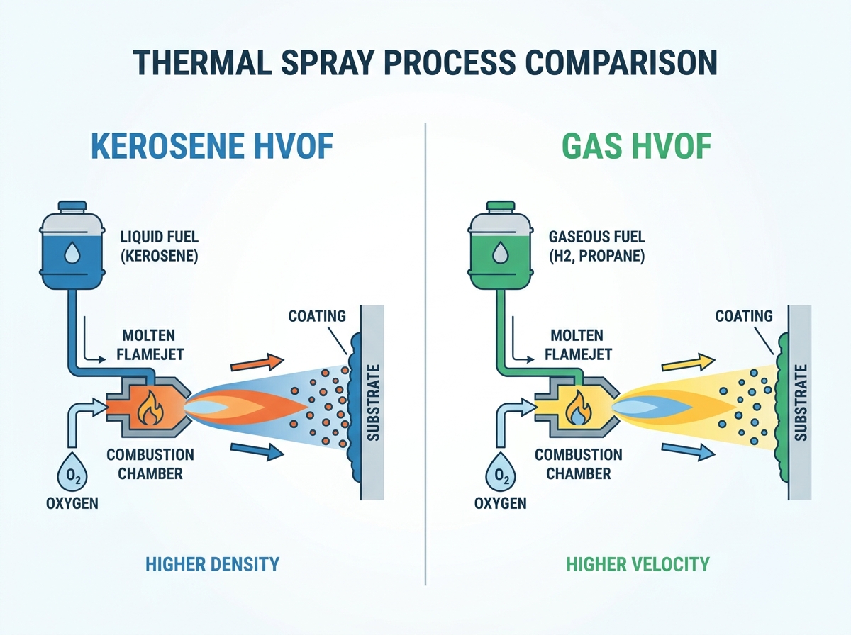
Kerosene HVOF vs Gas HVOF Trade-offs: Liquid fuel (kerosene) systems generally produce higher combustion pressures and particle velocities yielding denser coatings, while gas systems offer distinct operational, facility, and thermal management advantages.
Table of Contents
Thermal spray encompasses a specialized group of industrial coating processes. Technicians deposit finely divided metallic or nonmetallic materials in a molten or semi-molten condition. These particles accelerate toward a prepared substrate at high speeds. They impact the surface and form a highly engineered surface coating. The process allows engineers to apply exotic, high-performance materials onto standard structural metals. You gain the surface properties of ceramics or superalloys without the immense cost of manufacturing the entire part from those materials. Field applications range from rebuilding worn pump shafts to applying thermal barrier coatings on gas turbine blades.
The thermal spray spectrum includes several distinct technology categories. Flame spray utilizes basic oxygen-fuel combustion to melt and propel materials, offering a low-velocity solution for basic dimensional restoration. Twin-wire arc spray uses electrical currents to melt two converging conductive wires, providing high deposition rates for large-scale corrosion protection. Air Plasma Spray (APS) generates extreme temperatures via an ionized gas plume, making it ideal for melting high-temperature ceramics like yttria-stabilized zirconia. High-Velocity Oxygen Fuel (HVOF) maximizes kinetic energy over thermal energy. Each method balances thermal heat and kinetic impact differently. This balance dictates the final coating density, bond strength, and porosity.
Thermal Spray Process | Primary Heat Source | Typical Particle Velocity (m/s) | Typical Porosity (%) | Primary Industrial Application |
|---|---|---|---|---|
Flame Spray | Oxy-Fuel Combustion | 40 - 100 | 10 - 15 | Basic dimensional restoration, low-wear environments |
Twin-Wire Arc | Electrical Arc | 100 - 150 | 5 - 10 | Large-scale anti-corrosion (zinc/aluminum), boiler tubes |
Air Plasma Spray (APS) | Ionized Plasma Plume | 200 - 400 | 2 - 8 | Thermal barrier coatings, high-temperature ceramics |
HVOF | Supersonic Combustion | 600 - 1000+ | < 1 - 2 | Severe sliding wear, hard chrome replacement, cermets |
Understanding the adhesion mechanism dictates successful implementation. Welding melts the base material to create a metallurgical bond. Thermal spray does not melt the substrate. It relies strictly on mechanical bonding. High kinetic energy forces molten particles into microscopic surface asperities. Rapid solidification locks these particles in place instantly. This preserves the substrate's original structural integrity. It prevents the formation of heat-affected zones (HAZ). You avoid part warping, metallurgical degradation, and loss of base metal tensile strength.
Surface preparation dictates the entire success or failure of the coating system. Technicians begin with aggressive degreasing protocols. You must remove all cutting oils, fingerprints, and organic residues using industrial solvents or vapor degreasing tanks. Any residual hydrocarbons will vaporize upon contact with the thermal plume, creating gas pockets that cause immediate localized delamination.
The component then undergoes abrasive grit blasting. Aluminum oxide is the industry standard media for this step, though chilled iron grit is sometimes used for softer substrates. The angular grit removes existing oxides, rust, and microscopic surface contaminants. It creates a highly textured, jagged topography on the metal surface. Engineers measure this as an Ra (Roughness Average) profile. You must achieve the correct depth and angularity for the specific coating material. A typical HVOF application requires an Ra profile between 3.0 and 5.0 micrometers. Absolute cleanliness ensures maximum mechanical interlocking. If the molten particles cannot grip the jagged peaks and valleys, the coating will peel away under operational stress.
Masking occurs simultaneously with surface profiling. Technicians apply specialized silicone tapes, fiberglass fabrics, or custom-machined metal shadow masks to protect areas that must remain uncoated. These masking materials must withstand direct grit blasting impact and the extreme radiant heat of the spray torch.
Feedstock delivery systems utilize either powder or wire formats. Wire systems dominate arc spray and basic flame spray applications. Powder systems dominate plasma and high-velocity applications. Engineers categorize common coating materials based on the operational threat. Pure metals provide excellent galvanic corrosion resistance. Ceramics act as impenetrable thermal barriers in turbine engines. Cermets handle severe sliding and abrasive wear. Specialized polymers offer unique chemical resistance profiles.
Particle size distribution heavily influences the final coating architecture. Typical powder sizes range from 15 to 45 microns for HVOF, and up to 150 microns for plasma spray. Morphology also impacts flowability through the delivery hoses. Powders are manufactured using different methods, primarily agglomerated and sintered or cast and crushed. Agglomerated and sintered powders are spherical, flowing smoothly and melting evenly in the plume. Cast and crushed powders are blocky and irregular, which can cause feeding inconsistencies but often result in denser coatings if melted properly. The exact size and shape directly dictate the melting behavior in the thermal plume. This ultimately determines the final coating density and structural integrity.
The feedstock enters the core thermal source for rapid heating. This source might be a combustion flame, an electrical arc, or a high-energy plasma plume. The material absorbs heat in a fraction of a millisecond. It transitions from a solid state into a molten or semi-molten droplet. The core temperature of the plume dictates which materials can be successfully sprayed. Plasma plumes exceed 10,000°C, easily melting refractory ceramics. HVOF flames operate around 3,000°C, perfect for metallic binders in carbide matrices.
Propulsion requires immense aerodynamic force. A secondary compressed gas stream often atomizes the molten material. This gas stream accelerates the droplets toward the substrate at extreme speeds. The system must maintain a critical balance. You need enough thermal energy to reach the proper melting state. Simultaneously, you need enough kinetic energy to achieve maximum particle velocity. If particles are too hot, they vaporize or oxidize in flight. If they are too cold, they bounce off the substrate, drastically reducing target transfer efficiency.
Modern facilities utilize 6-axis robotic arms to manipulate the spray torch. Manual spraying introduces human error, inconsistent standoff distances, and uneven traverse speeds. Robotic manipulation guarantees exact parameter control. The torch maintains a strict 90-degree angle to the substrate at a precise standoff distance, typically between 8 to 15 inches depending on the specific process.
Molten droplets strike the prepared substrate with violent force. They flatten instantly into microscopic structures called splats. These splats rapidly cool, shrink, and solidify in microseconds. They interlock one on top of another as the spray torch passes over the component. The continuous impact of millions of droplets builds the coating thickness layer by layer.
This process builds a distinct lamellar structure. Under a microscope, the coating looks like layered, flattened pancakes. The chosen spray environment inherently influences this structure. High-velocity systems pack the splats tightly together, minimizing splat boundaries. Lower-velocity systems leave microscopic voids between the layers. Some oxidation occurs as the particles travel through the ambient air. The specific torch design and gas mixture control the extent of this in-flight oxidation. Excessive oxide inclusions weaken the cohesive strength between the individual splats.
Thermal spray coatings do not emerge from the process perfectly smooth. As-sprayed surfaces exhibit a rough, sandpaper-like texture. Dimensional tolerances rarely meet final engineering prints directly off the torch. The coating is intentionally applied slightly oversize to allow for final machining.
Secondary finishing operations are mandatory for precision components. Standard single-point turning tools cannot cut hard cermet coatings. Precision diamond grinding achieves exact dimensional tolerances. Lapping processes provide mirror-like surface finishes for hydraulic seals and bearing journals. In highly corrosive environments, technicians apply specialized polymer, phenolic resin, or epoxy sealers. These sealants penetrate and close any residual microscopic porosity via capillary action. This prevents corrosive media from migrating through the lamellar structure and attacking the base metal.
Standard flame or twin-wire arc spray lacks sufficient kinetic energy for severe industrial applications. Ultra-dense, low-porosity coatings demand significantly more impact force. Severe wear environments destroy standard porous coatings rapidly. Aerospace landing gear, oil and gas gate valves, and heavy mining equipment require superior surface protection. Traditional methods simply cannot pack the particles tightly enough to withstand extreme abrasive and erosive forces.
HVOF solves this engineering challenge completely. It stands as the premier process for depositing hard cermets. Tungsten Carbide and Chromium Carbide thrive in HVOF systems. The technology relies on a massive kinetic-to-thermal energy ratio. It heats the particles just enough to soften the metallic binder (like cobalt or nickel), then accelerates them to supersonic speeds. This minimizes material degradation during flight. It prevents excessive oxidation before the particle hits the substrate. The result is a nearly impenetrable, highly cohesive wear surface that routinely outperforms hard chrome plating.
Evaluating kerosene HVOF vs gas HVOF requires a deep understanding of combustion physics. Both systems utilize a convergent-divergent de Laval nozzle to achieve supersonic gas flows. However, the fuel state fundamentally alters the internal chamber dynamics, particle acceleration profiles, and final coating metallurgy.
Gas HVOF systems utilize gaseous fuels for combustion. Technicians mix hydrogen, propylene, propane, or natural gas with high-pressure oxygen. The gases enter the combustion chamber and ignite continuously. The resulting exhaust gases expand rapidly and exit through the nozzle.
The combustion dynamics present specific characteristics. Gas systems operate at lower combustion chamber pressures compared to liquid systems, typically hovering between 60 and 90 psi. This results in slightly lower overall particle velocities. However, gas combustion produces highly stable, easily controllable thermal profiles. The flame temperature remains consistent. This makes gas systems excellent for spraying materials that require precise heat input without risking vaporization. Gas systems also utilize shorter barrel lengths, making the torches slightly more maneuverable.
Kerosene HVOF systems utilize atomized liquid fuel. High-pressure oxygen atomizes the liquid kerosene into a fine mist inside the combustion chamber. The mixture ignites, creating a massive volumetric expansion. Liquid fuels contain significantly higher energy density than gaseous fuels.
This creates distinct combustion dynamics. The liquid fuel generates much higher combustion chamber pressures, routinely exceeding 120 to 150 psi. This pressure forces the exhaust gases through the nozzle at superior velocities. Gas speeds often exceed Mach 2. The particles injected into this stream absorb massive kinetic energy. They strike the substrate with immense impact force, flattening completely upon contact. The liquid process generally runs cooler than high-energy gases like propylene, protecting sensitive carbide structures from thermal degradation.
Porosity levels differ significantly between the two methods. Kerosene systems typically achieve less than 1% porosity. The extreme impact energy forces the splats to conform perfectly to the underlying layers. This creates an exceptionally dense lamellar structure. Gas systems produce excellent coatings, but they often exhibit slightly higher porosity levels (1% to 2%) due to the lower kinetic impact.
Compressive stress dictates coating longevity and maximum thickness. Kerosene HVOF imparts much higher compressive stresses into the coating layer. Engineers measure this using Almen strip testing. Compressive stress prevents crack propagation. It allows engineers to apply thicker coating limits before the risk of spallation occurs. Gas HVOF often generates more tensile stress, limiting the maximum achievable thickness before the coating pulls itself apart.
Carbide degradation requires careful monitoring. Gas HVOF runs hotter depending on the specific fuel gas used. Propylene burns very hot. This leads to higher decarburization of sensitive materials like Tungsten Carbide-Cobalt (WC-Co). The carbon burns out of the matrix, forming brittle W2C phases and weakening the final coating. The cooler, faster kerosene process preserves the original carbide structure much better, resulting in higher retained microhardness.
Performance Metric | Gas HVOF (e.g., Propylene/Hydrogen) | Kerosene HVOF (Liquid Fuel) |
|---|---|---|
Combustion Chamber Pressure | Low to Moderate (60 - 90 psi) | High (120 - 150+ psi) |
Particle Velocity | High (Mach 1 to Mach 1.5) | Very High (Mach 2+) |
Typical Coating Porosity | 1% to 2% | Less than 1% |
Residual Stress Profile | Neutral to slightly tensile | Highly compressive |
Carbide Degradation Risk | Moderate (depends on gas temperature) | Low (cooler, faster flight time) |
Fuel availability dictates long-term operational logistics. Kerosene is a globally available commodity. It is easy to source and easily stored in standard liquid tanks. Industrial gases require specialized high-pressure storage cylinders or bulk liquid tanks. You must negotiate complex delivery contracts. Managing gas boil-off and cylinder rental fees adds continuous logistical overhead to the operation.
Deposition rates heavily favor liquid fuels. Kerosene systems generally offer higher spray rates, often pushing 10 to 15 kilograms per hour for carbide powders. They provide better target transfer efficiency, meaning more powder sticks to the part and less bounces off into the dust collector. This rapid deposition reduces labor hours. It cuts machine time significantly when processing large industrial components like hydraulic rams or massive calendar rolls.
Safety risks vary drastically between the two fuel types. Storing high-pressure, highly flammable gases like hydrogen or propylene presents severe facility risks. A gas leak can rapidly fill a room and ignite explosively. Liquid kerosene is much safer to store in bulk. It requires a specific ignition source and atomization to burn effectively.
Facility infrastructure reflects these inherent safety risks. Gas systems require complex manifolding. You must implement strict, automated leak detection protocols. Local fire codes often mandate the installation of expensive blast walls and specialized ventilation systems. Kerosene requires standard liquid handling pumps. The atomization infrastructure is straightforward and much easier to permit in standard industrial parks.
Choose kerosene systems for applications requiring absolute maximum wear resistance. High density and extreme microhardness are paramount for specific components. Hydraulic rods in heavy excavators, massive ball valves in pipelines, and slurry pump housings are perfect candidates. The dense, low-porosity structure prevents abrasive media from penetrating the surface.
Specify kerosene when applying very thick coatings. Managing residual compressive stress is critical when building up heavily worn dimensions. The compressive nature of the kerosene process prevents catastrophic cracking as the coating grows thicker. High-volume production environments also benefit greatly. The superior deposition speed and simplified fuel logistics heavily favor liquid fuels for continuous manufacturing lines.
Choose gas systems for applications requiring highly specific thermal profiles. Sensitive superalloys or finer powder distributions require precise heat control to melt properly without vaporizing. Gas flames offer excellent tunability for these niche metallurgical requirements.
Specify gas systems for facilities already equipped with extensive industrial gas infrastructure. If your plant already utilizes bulk hydrogen or propylene for other processes, adding liquid fuel handling becomes redundant. Finally, internal diameter (ID) spraying relies heavily on gas. Specialized compact gas HVOF torches are readily available. They are far more maneuverable inside small pipes and cylinder bores than bulky liquid-cooled kerosene torches.
Overheating the substrate during HVOF application is a severe risk. The massive heat from the supersonic plume transfers rapidly into the base metal. This alters the base metal's mechanical properties. It causes severe dimensional distortion, turning a straight shaft into a warped, unusable piece of scrap.
Mandate strict part-cooling protocols to mitigate this risk. Use targeted compressed air jets or liquid CO2 cooling systems directed at the back of the part or directly adjacent to the spray footprint. Continuously monitor interpass temperatures using calibrated infrared sensors. You must keep the substrate temperature strictly below 150°C throughout the entire spray process.
Invisible sub-surface delamination ruins critical parts in the field. Excessive porosity or un-melted particles compromise the coating integrity entirely. You cannot visually inspect a coating and guarantee its mechanical bond strength. Poor parameters lead to catastrophic failures under load.
Require strict adherence to standardized ASTM testing protocols. Conduct bond strength testing using the ASTM C633 standard to measure the exact tensile pull-off strength. Perform detailed metallographic evaluation of cross-sections using ASTM E2109 guidelines to measure exact porosity percentages. Execute microhardness testing using Vickers or Knoop scales prior to authorizing any full-scale production runs.
Define your required coating specifications immediately, detailing exact porosity limits, hardness targets, and operating environment threats.
Evaluate your existing facility infrastructure to determine if high-pressure gas storage or liquid fuel handling aligns better with your safety protocols.
Consult with a certified thermal spray provider to run metallographic test coupons using both methods for your specific powder choice.
Verify complete adherence to ASTM C633 bond strength testing standards before authorizing full-scale production runs on critical components.
A: The primary difference lies in the fuel state and resulting combustion dynamics. Liquid kerosene generates higher combustion chamber pressures and superior particle velocities. This results in denser coatings with higher compressive stress. Gas HVOF uses gaseous fuels like hydrogen or propylene, offering lower velocities but highly stable, controllable thermal profiles for sensitive materials.
A: No. Thermal spray is considered a cold process for the substrate. The base metal is typically kept below 150°C using active cooling methods like targeted air jets or liquid CO2. This prevents metallurgical changes, eliminates heat-affected zones (HAZ), and stops dimensional warping.
A: Coating thickness limits are dictated by residual stress buildup within the lamellar structure. Gas HVOF coatings are often limited to thinner applications to prevent tensile stress cracking. Kerosene HVOF imparts higher compressive stress, allowing for significantly thicker coating limits before the risk of spallation occurs.
A: HVOF is primarily used to apply high-performance cermets and specialized metal alloys. Common materials include Tungsten Carbide, Chromium Carbide, and various superalloys like Inconel, Hastelloy, and Stellite. These materials provide exceptional wear resistance, corrosion protection, and high-temperature stability.
A: Thermal spray relies entirely on mechanical interlocking for adhesion, not metallurgical fusion. Proper abrasive grit blasting creates the necessary surface roughness and angular profile. Failing to achieve absolute cleanliness and the correct topography accounts for the vast majority of premature coating delamination failures.
A: Kerosene HVOF is generally considered safer regarding storage and facility infrastructure. Liquid kerosene is easily stored in standard tanks. Gas HVOF requires storing high-pressure, highly flammable gases. This necessitates complex manifolding, strict leak detection protocols, and often the installation of expensive blast walls.